Headset With Microphone Wiring Diagram
White is the mic and. With this sort of an illustrative manual, you’ll be able to troubleshoot, stop, and full your tasks without difficulty.
Iphone Headphone Mic Wiring Diagram Wiring Diagram and Schematic

Fancasee 2 pack replacement 3 5mm female jack to bare wire open end trrs 4 pole stereo 1 8 plug connector canada.

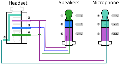
Headset with microphone wiring diagram. To this day the terms tip ring and sleeve coined by the telephone industry are used to identify the three circuits. Diy replaceable headphone cord mod to use sony mdr 7506 with a straight coord yes like beats but still better. To convert to (m2) mm threaded connector and use all the following earpieces and headsets:
Otherwise, the arrangement will not function as it ought to be. This headset plug design was in common usage in at least a. Use the lighter to burn off the white insulation.
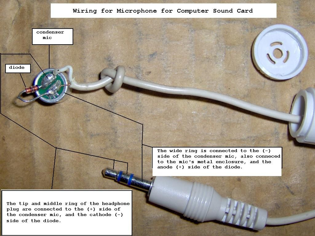
It is rugged otherwise, i'd be wiring a custom trrs adaptor. Sony playstation headset wiring diagram all dreamgear grx 340 ps4 hd png transpa image pngitem. Connect headphone and microphone jacks with 20 22 gauge wire preferably 22 gauge as shown in figure 7 below and page 7 figure 8.
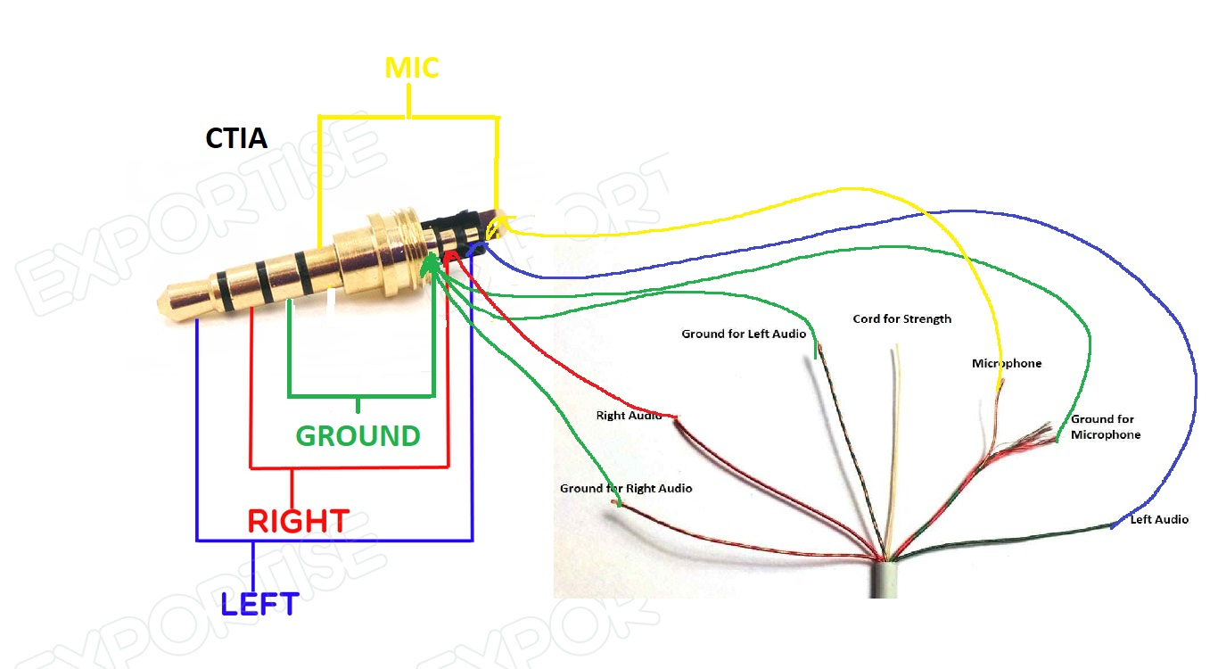
And nexus one headset controls: Ring = right earpiece signal; The little white wire inside the red and green wire is the mic ground.
Wired for icom radios and your yamaha. What do these headphone wire colours mean copper blue green and intertwined with quora. I got the idea from someplace that the tip is the mono mic (the combo jack does not support stereo input).
Determine which figure best describes your headset, and install the modules according to that figure. Generally, a radio manufacturer will wire their microphones the same so that the microphones are interchangeable between their radios, however, this is not always the case. Jumper 1 to shell pin 1 = s 10k pin 2 to w 1uf pin 2 to w diagram wiring for 5v.
Inner copper wire is the microphone signal, outer sheath is the microphone ground. There are two things that will be present in any headphone with mic wiring diagram. Issue, solution and the aftermath articles shows a circuit diagram for samsung headset.
The yamaha cm is a very popular headset for amateur radio use. Five different configurations are shown below. I went and got one to do the design with and after a couple weeks it's done for icom.
Galaxy s4 headset mic & button wiring schematic pinout???? The mic + connection seems fairly obvious too, on the ring of the mm. Usb audio hyperx cloud ii not able to do speaker and headset simultaneously overclock net.
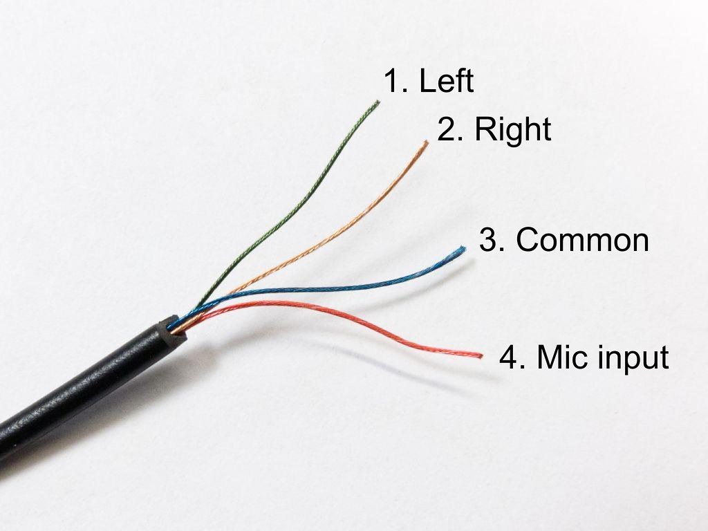
This boom microphone wiring harness for 1/5. Some mic wiring diagrams for ranger, realistic alan, cobra, ge, uniden, yaesu, kenwood, icom radios. After you cut open the plastic insulating sheath you’ll find 5 separate wires:
Wikipedia suggests youre likely going to want to reattach it with the tip hooked to the left. Microphone wiring alan cobra uniden president galaxy and more microphone wiring diagrams cb mic wiring excellent resource for. About press copyright contact us creators advertise developers terms privacy policy & safety how youtube works test new features press copyright contact us creators.
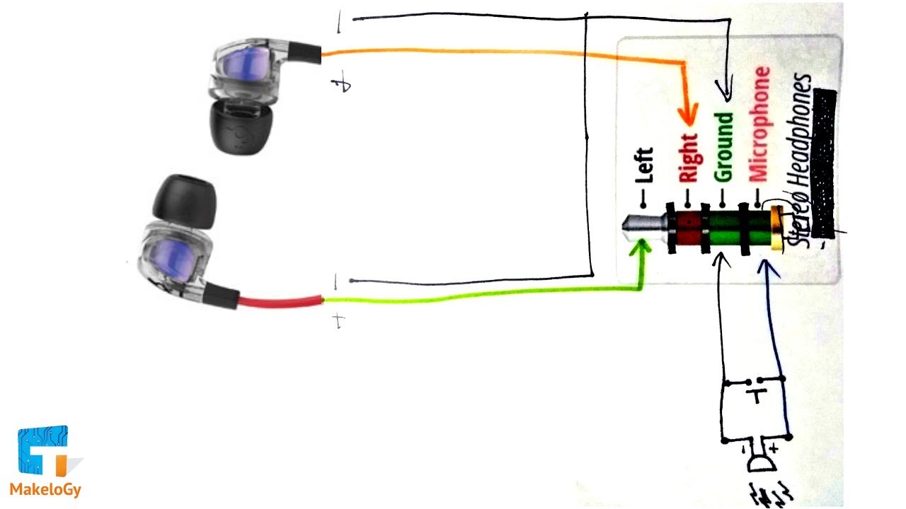
Android device external mic wiring. Headphone with mic wiring diagram wiring diagram is a simplified up to standard pictorial representation of an electrical circuit. This means the bare copper wire is ground.
The red wire then, is the left channel, and blue is the right channel and are each connected to the ground copper wire, “upstream” on the headset end at the speaker drivers. Red and green sheath with a copper wire inside: The basic design for this style of connector has roots in the design for a plug and jack set used with headsets.
I got my samsung s4 to detect external when i used 1.5 kom resistor between mic pins (the same trick did not seem to work on denver tablet for some reason). Diagrams for the microphone connections on many of the common cb radios, as well as some popular amateur radio transceivers. Dell's documentation regarding anything audio is very sparse.
Each component should be set and connected with other parts in particular way. Choose hardwired option for p48: Choose hardwired option for p48
Different manufacturers may wire their microphones differently. July 9, 2020 · wiring diagram. Removing action camera mic mic is connected by the terminals on its circuit board.
3 5mm audio jack wiring diagram wiring diagram name 4 pole 3 5mm jack wiring diagram wiring diagram contains numerous in depth illustrations. This form of microphone connector has been around since world war ii. Here’s the wiring scheme for apple’s ahj headset connector:
The first component is symbol that indicate electrical component in the circuit. Wiring diagram consists of numerous in depth illustrations that present the connection of varied things. Nokia has somewhat thrown in the towel on its omtp standard by developing a way for their second generation of lumia phones to sense what kind of headset is plugged in and act accordingly.
Jumper 1 to shell pin 1 = s+b pin 2 = r diagram wiring for 5v. Wiring a pair of sony earplugs cable to new 3 5mm jack ecoustics com. The jack is meant to work with a typical smart phone headset so if you find wiring for one of those then that is it.
A circuit is generally composed by various components. Nokia headset handsfree hdb 5 connector and schematics pinout diagram pinouts ru. I have a latitude e5420 also but use an external usb sound card.
The headset plug diameter was only a two circuit plug (sleeve and tip) and 0.25 in diameter. The other thing which you will come across a circuit diagram would be lines. For example, cobra 4 pin radios are wired 1) shield 2) audio 3) transmit 4) receive while midland 4 pin radios are wired 1) audio 2) shield 3) receive.
The trrs audio plug is found on iphone headphones and other headphones that have a microphone. Tip = left earpiece signal; Choose hardwired option for p48:
Sony mdr 7505 service manual pdf manualslib. Jumper 1 to shell pin 1 = s+b pin 2 = r use w4 type headset diagram wiring for 5v.
Typical Computer Headset Wiring Diagram Barkingmode.

Headset/Mic jack wiring VAF Forums

Usb Headset With Mic Wiring Diagram USB Wiring Diagram

Final Soultion Why Most Headsets Won't Work Android Forums At Headphone With Mic Wiring
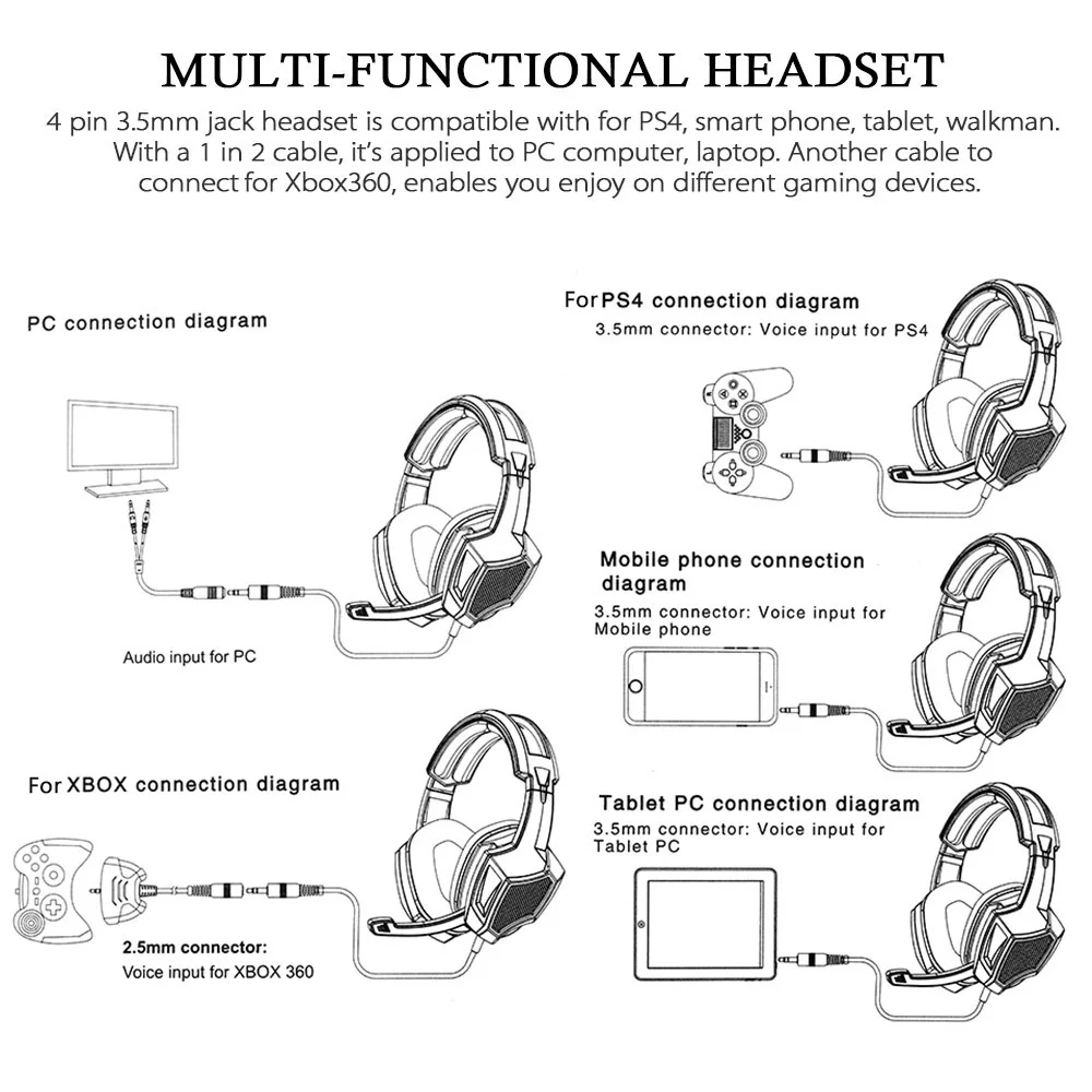
Using your Mobile Headset on a PC
Wiring Diagram Of Headphones With Mic PALOTAKENTANG
Wiring Diagram Building Noise Canceling Headphones Microphone schematic and wiring diagram

Typical Computer Headset Wiring Diagram Barkingmode.

Wiring Diagram For Headphones With Mic

Stereo Headset With Microphone Wiring Diagram Car Wiring Diagram
Headset With Mic Wiring Diagram How to repair earphones mic. How to Fix "Mic Volume Too Low or
Usb Headset With Microphone Wiring Diagram USB Wiring Diagram

Usb Headset With Microphone Wiring Diagram Search Best 4K Wallpapers
Headphone Jack With Mic Wiring Diagram Wiring Diagram Schemas
Usb Headset With Mic Wiring Diagram USB Wiring Diagram

Nice Headphone Wiring Diagram Contemporary Electrical Circuit Headphone, Headphone with mic
David Clark Mic Wiring Diagram Manual EBooks Headphone With Mic Wiring Diagram Wiring Diagram
Headset wiring I took apart two of these headsets and the … Flickr
3FAF62 Pc Headset Mic Wiring Diagram Wiring Library