Extension Board Circuit Diagram
Diy electric extension board wiring: You can also experiment with the extension board when using it standalone, ie.
Phone Extension Cord Wiring Diagram diagram geometry

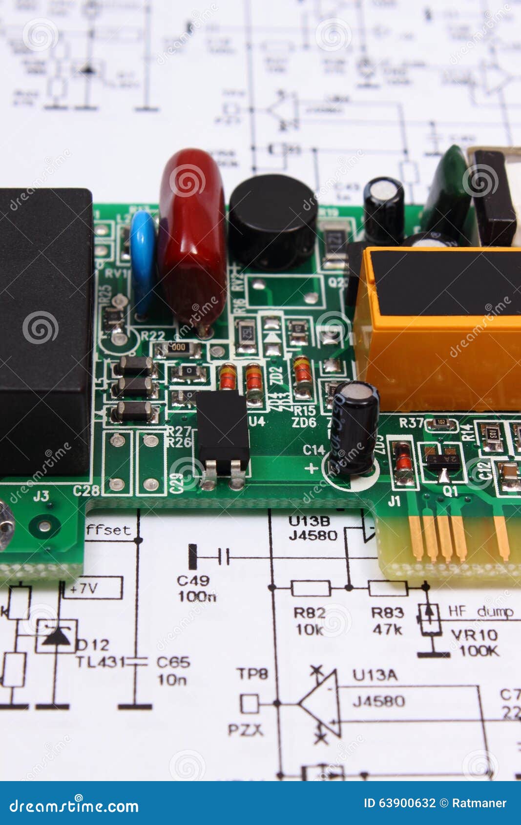
This can be made much smaller than a discrete circuit made from independent electronic components.

Extension board circuit diagram. Electrical wiring extension cord wiring diagram an extension cord also called an extension lead or power extender is a power supply expanding box. Extension board circuit diagram extension board connection diagram. Get results from multiple engines.
Its components are shown by the pictorial to be easily identifiable. Ics can be made very compact, having up to several billion transistors and other electronic components in an. Extension board is used for many purposes to extend the mains.
Circuit diagram electrical extension board it is far more helpful as a reference guide if anyone wants to know about the home’s electrical system. Below is the given wiring diagram of single phase distribution board with rcd in both nec and iec electrical wiring color codes. It shows current voltage as well as ampere being consumed at the real time.
They must be diagnosed and repaired as soon as possible. A diagram that represents the elements of a system using abstract, graphic drawings or realistic pictures. This is followed by measurement and cutting of cable length to be used for the extension box construction (the cable with thickne ss of 3.5mm in
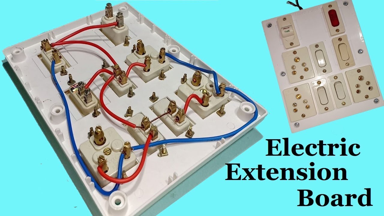
0cbe4ac circuit diagram 3 phase motor forward reverse. It is a lengthy flexible electrical cable with a plug at one end and multiple sockets on the other end. Learn whats inside in electrical extension board.extension board diagram circuit.like, share & subscribe learn electrical engineering channel.
A power point wiring has a circuit similar to a normal 3 pin socket connection with switch control. 0f95957 citroen c crosser wiring diagram. This can be made much smaller than a discrete circuit made from independent electronic components.
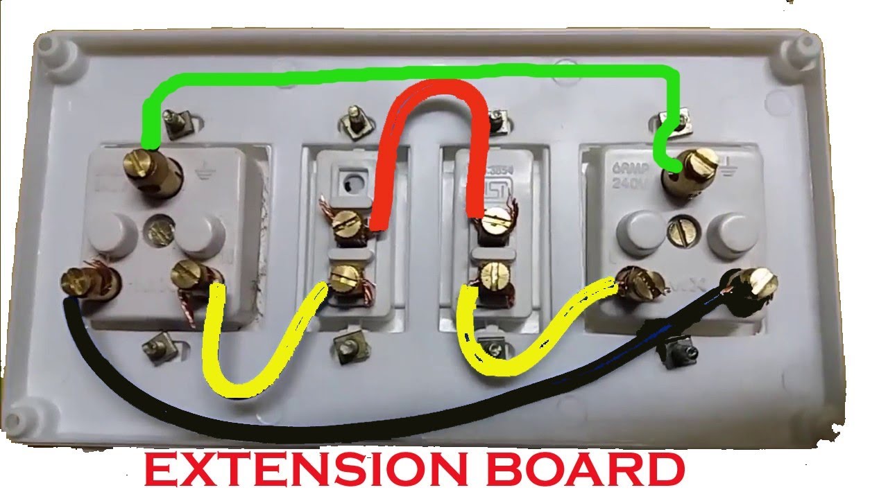
And each of the sockets is independently controllable via separate switches. Extension cord with switch circuit diagram posted by margaret byrd posted on june 6 2018 extension cord wiring diagram electrical wires cable switch board connection 4 way t loop full importance of using schematic diagrams. Deriving these positions, students fixed the pattress box on the board using screw.
0d3f13c circuit diagram jvc tv. Download circuit diagram electrical extension board pdf how to wire a socket with a switch to an electrical supply, the below given diagram shows a simple. Board, mapping out accurate and neat alignment which fits the setting of the extension box.
Ics can be made very compact, having up to several billion transistors and other electronic components in an. Circuits and logic diagram makes it easy to design and share diagrams using a wide range of component and the description of logic gates in combination to represent a logic expression. Take care not to cut the three wires inside.
An integrated circuit (also referred to as an ic, a chip, or a microchip) is a set of electronic circuits on one small plate (chip) of semiconductor material, normally silicon. Circuit diagram of extension board posted by margaret byrd posted on november 11 2017. Pdf file of the extension board circuit diagram can be obtained from the following link:
0e3c80d citroen bx 16v wiring diagram. The same description and detailes can be used as mentioned for the above fig 1. Electric extension board circuit diagram / make your own extension board 13 steps with pictures instructables :
Is the least efficient diagram among the electrical wiring diagram. 0cbf0de circuit diagram of xnor gate. A diagram that uses lines to represent the wires and symbols to represent components.
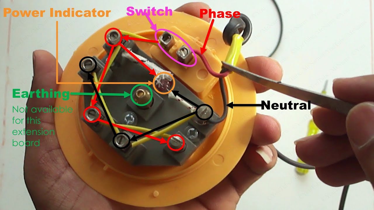
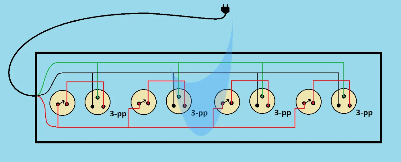
An integrated circuit (also referred to as an ic, a chip, or a microchip) is a set of electronic circuits on one small plate (chip) of semiconductor material, normally silicon. Presented here is an instructable to make your own extension board. Grey= phase 1 or line1, black= line 2, brown= line 3, blue = neutral and green= earth conductor.
In the above extension board diagram the neutral and line wire supply comes to the board. A pcb mechanically supports and electrica. Schematics of spresense extension board.
Spike guard diagram extension board surge protector protector how to make an electric extension board at home with 1 switch and 3 sock extension board electricity extensions plug wiring diagram plugs extension cord wire diy youtube electric board switches extension board how to make. Make your own extension board: The spresense camera board has the sony isx012 image sensor mounted together with a lens.
Extension board is used for many purposes to extend the mains line. 12 extension board circuit diagram. 30 amp generator extension cord.
Print or download electrical wiring diagrams. The extension board is designed for being plugged onto the base board. It allows using a variety of sensors such as air pressure, humidity and temperature, as well as displays, gas meter, etc.
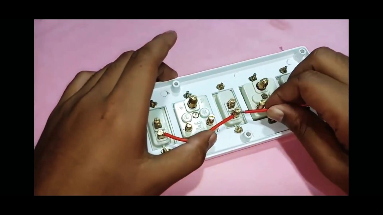
Electrician circuit drawings and wiring diagrams youth explore trades skills 3 pictorial diagram: 0d89b01 circuit diagram of 8086 microprocessor. But it is necessary to have correct knowledge about wiring in the board.
In this instructable i will tell you whole process of making this homemade electric extension board step by step. So, whenever the switch of the extension board on/off it just breaks the neutral line to the socket of the extension box but the phase line of the socket always remains charged. It is really very useful electric board.
A circuit diagram is a visual display of an electrical circuit using either basic images of parts or industry standard symbols. In four easy steps heres how to replace an extension cord plug. Ad search for relevant info results.
Circuit diagram for superregenerative receiver built by ge labs: 0cebda5 citroen picasso fuse box layout. The neutral wire is connected to the voltmeter and each.
In this step by step instructable, i wil… A buzzer my be connected as well for alarm output.
IoT Based Small Extension Board
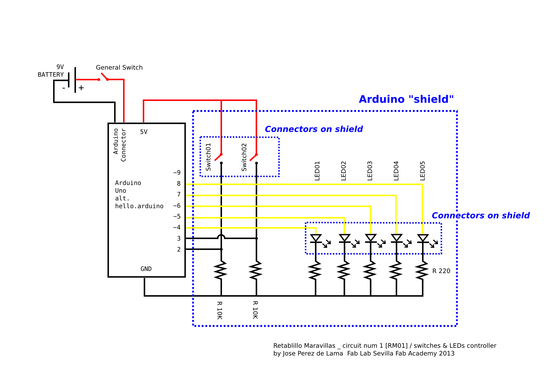
Fab Academy 2013 Fab Lab Sevilla final project electronics
Electric Quiz Board Circuit Diagram / Free Usb Mp3 Player
Extension Board Wiring Connection DemaxDe

Extension board wiring YouTube
How to make Extension Board/Cords at home Deepak Gadgets

Extension Cord Wiring Diagram Read typically the

House Wiring Circuit Board

Ac Wiring Board Wiring Diagram Networks
Home Electrical Switches Wiring Wiring Diagram Library

Extension cord wiring diagram Mechatrofice

55 Switch Socket Connection Diagram Wiring Diagram Plan

Extension cord wiring diagram
EEE Made Easy (My Note Book ) How to make an extension box

3 pin Extension board wiring & electrical basis wiring
Simple Extension Board Circuit Diagram See More on Home
How to Make Electric Extension Board at Home

[TA_7774] Arduino Uno Circuit Diagram Schematic Wiring

How Series Parallel Electrical Testing Board Work and Its
