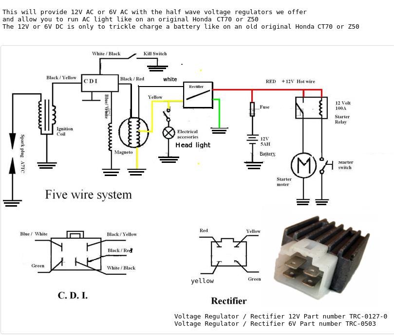
4 Wire Regulator Rectifier Wiring Diagram
5 wire regulator rectifier wiring diagram 3 pin regulator rectifier wiring diagram 3 wire rectifier diagram kbpc5010 bridge rectifier wiring diagram how to wire stator and rectifier 12v rectifier regulator diagram motorcycle. The generator itself is located in or on the engine and on most bikes there is a.
4 Pin Regulator Rectifier Wiring Diagram Atkinsjewelry

4 wire regulator rectifier wiring diagram.

4 wire regulator rectifier wiring diagram. Wiring diagram for voltage regulator. Wiring your bikes charging circuit has never been so easy. Regulator rectifier diagram here you are at our site this is images about regulator rectifier diagram posted by maria nieto in wiring category on may 08 2019.
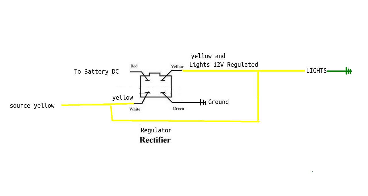
› see more product details Diagram firenzee com, 150cc scooter wiring diagram wiring diagram and schematics, 4 pin regulator scooter doc forum, 150cc gy6 engine diagram wordpress com, yerf dog 150cc wiring diagram go kart buggy depot, advanced 6 wire rectifier wiring diagram gy6 voltage, gy6 rectifier regulator wiring diagram Trail tech stators have yellow lighting leads.
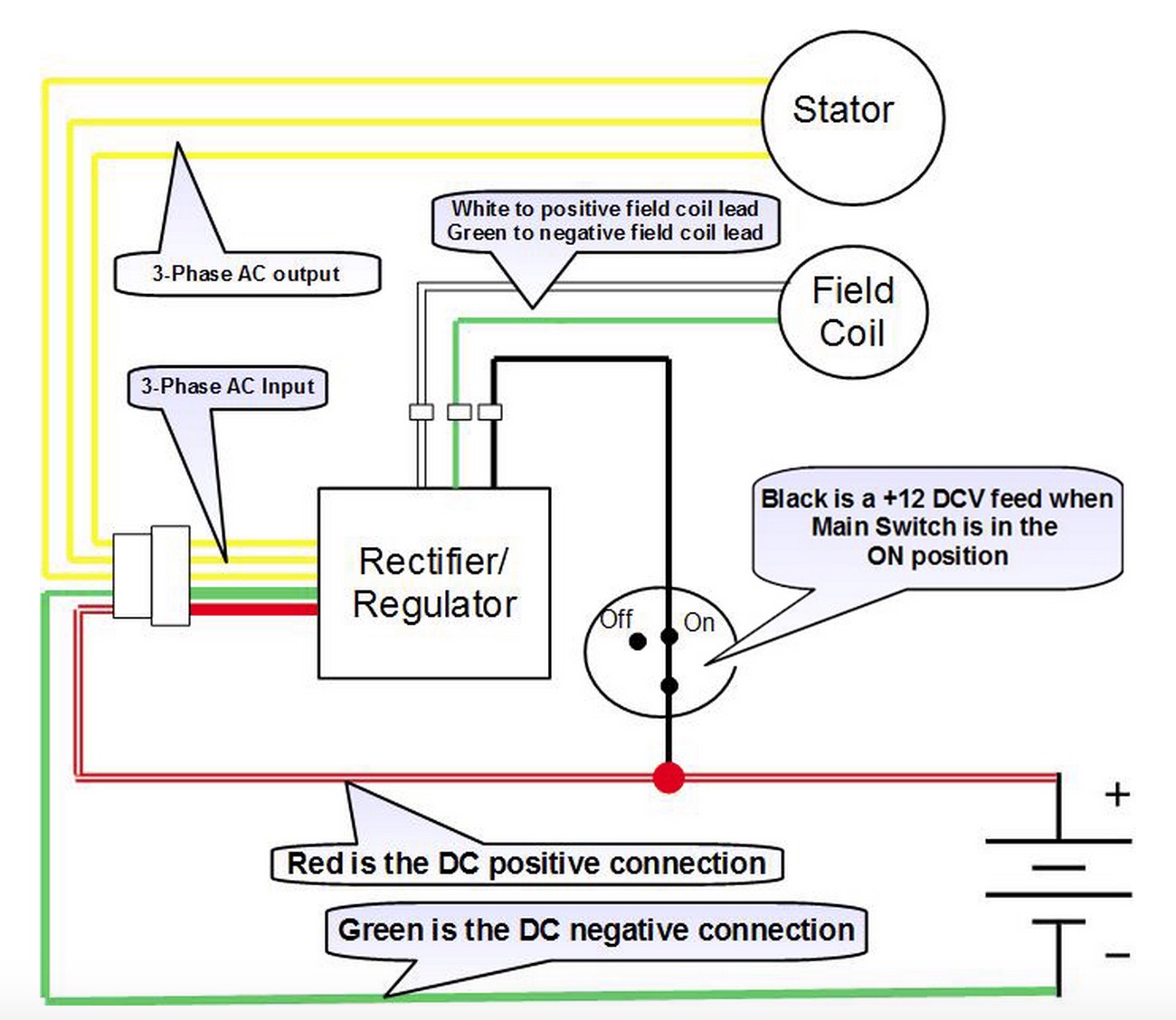
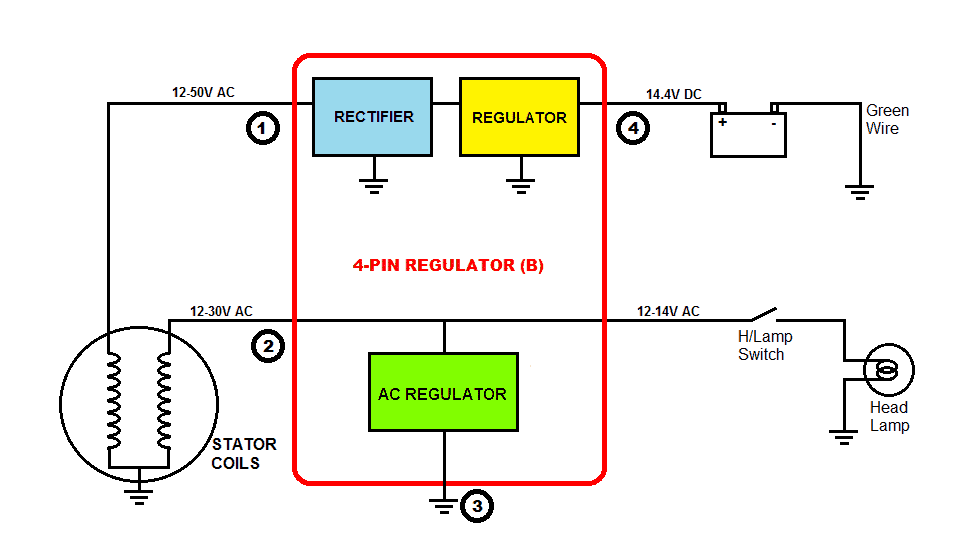
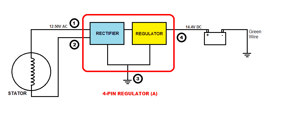
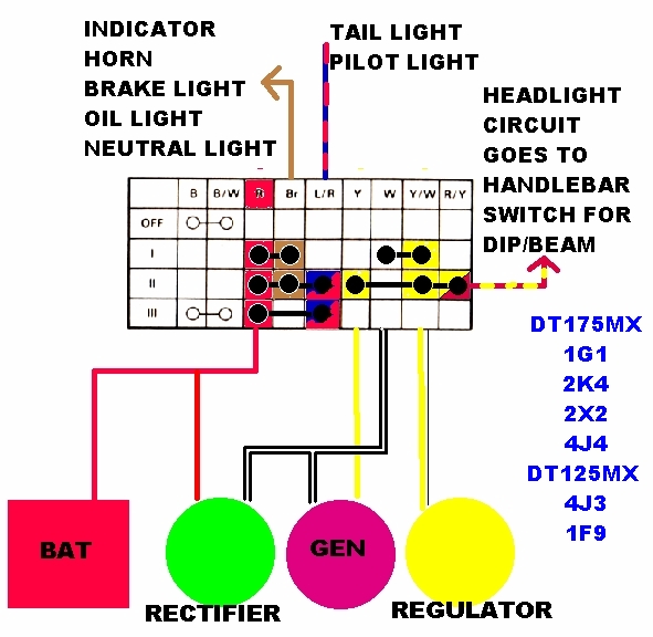
Connect to lighting leads from stator. The rectifier outputs about dc14.5 voltage can charge for 12v lead acid battery and supply power for 12v bulb and so on. In this system, both the ends of the winding go to the rectifier section which converts ac to dc voltage and then the regulator section regulates to 14.4v as discussed above.
This diagram provides advice of circuit. Wingsmoto rectifier regulator 4 wires voltage atv gy6 50 cc scooter.kohler rectifier wire diagram: Make sure to find a solid ground.
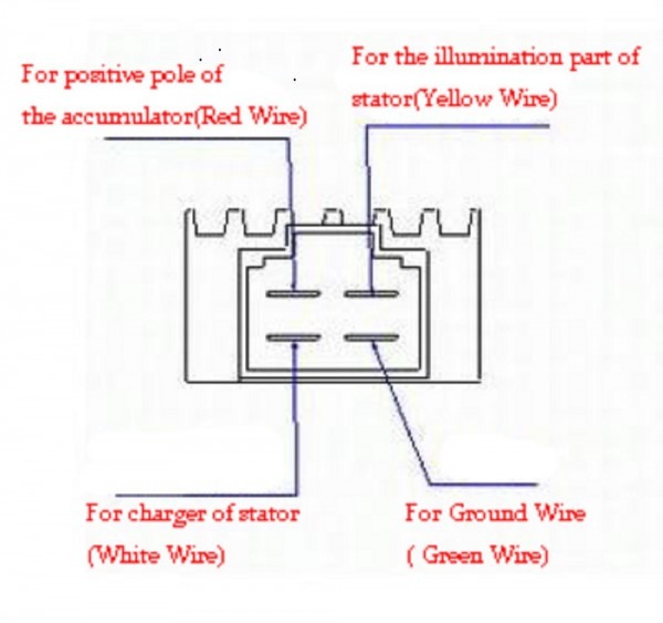
This atv, dirt bike, and scooter rectifier (voltage regulator) has 4 active pins as shown in the image. The color code remains the same. Buy voltage regulator rectifier for kohler 41 s 41 s 25 s:
(plastic 4 pin terminal + 4 male spade terminals included.) 3 wire stock rectifier. Each part should be placed and linked to different parts in particular way. A few notes i pulled this schematic out of an older scooter repair manual.
How to wire a gy6 scooter regulator rectifier and how it all works part 3 the regulator duration. The casing does not need to be grounded. See more articles in category:
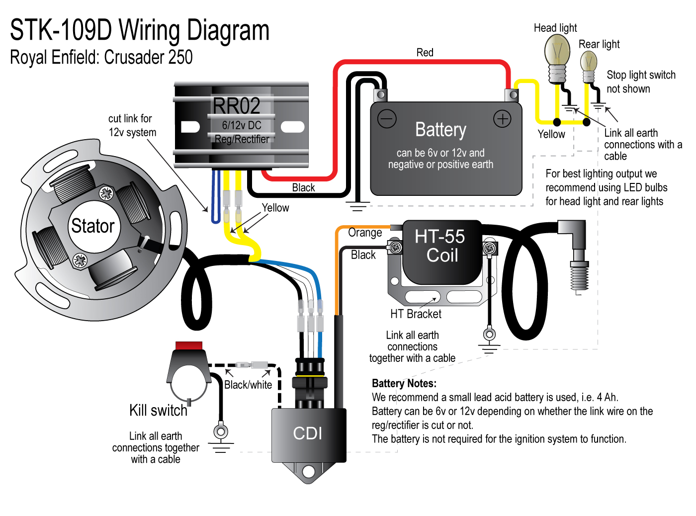
Use included wire with eye terminal to ground out the green wire on the regulator rectifier. However this diagram is a simplified version of this arrangement. However, this diagram is a simplified version of this arrangement.
6 volt solid state regulator rectifier. This is images about kohler rectifier wire diagram posted by jeremy kennard in kohler category on oct 26, you can also find other images like wiring diagram, parts diagram, replacement. The rectifier comes with free wire adapter connect cable.
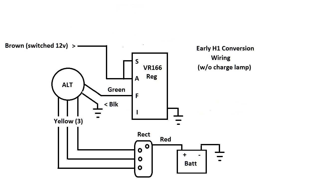
The battery and charging system) and found this diagram: Regulator rectifier diagram here you are at our site this is images about regulator rectifier diagram posted by maria nieto in wiring category on may 08 2019. This regulator rectifier has to work together with a 12v battery.
6 pin regulator rectifier wiring diagram. Here is a picture of the 6 wire r/r unit and its associated connectors. This is a brand new voltage regulator rectifier fit for motorcycle and boat motors, diy engines and so on.
Referring the the ubiquitous 200 page service and repair manual that's floating around in pdf format, i went to page 156 (chapter 14: This makes the procedure for assembling circuit simpler. Mount new part where the old rectifier was.
The diagram offers visual representation of the electrical structure. 1x 4 wire regulator rectifier 1x wiring diagram. Provided below is an online pdf document for lamberts bikes 3 phase 6 wire regulator rectifier wiring diagram.
Marvellous motorcycle regulator rectifier wiring diagram ideas size. 6 wire regulator rectifier wiring diagram 4 wire rectifier wiring diagram 4 wire voltage regulator wiring diagram rectifier connection diagram 6 wire voltage regulator wiring diagram kbpc5010 bridge rectifier wiring diagram 3 pin regulator rectifier wiring diagram. Otherwise, the arrangement will not work as it ought to be.
If without 12v battery, the output voltage will be much higher. See more articles in category: The article was submitted by mr.
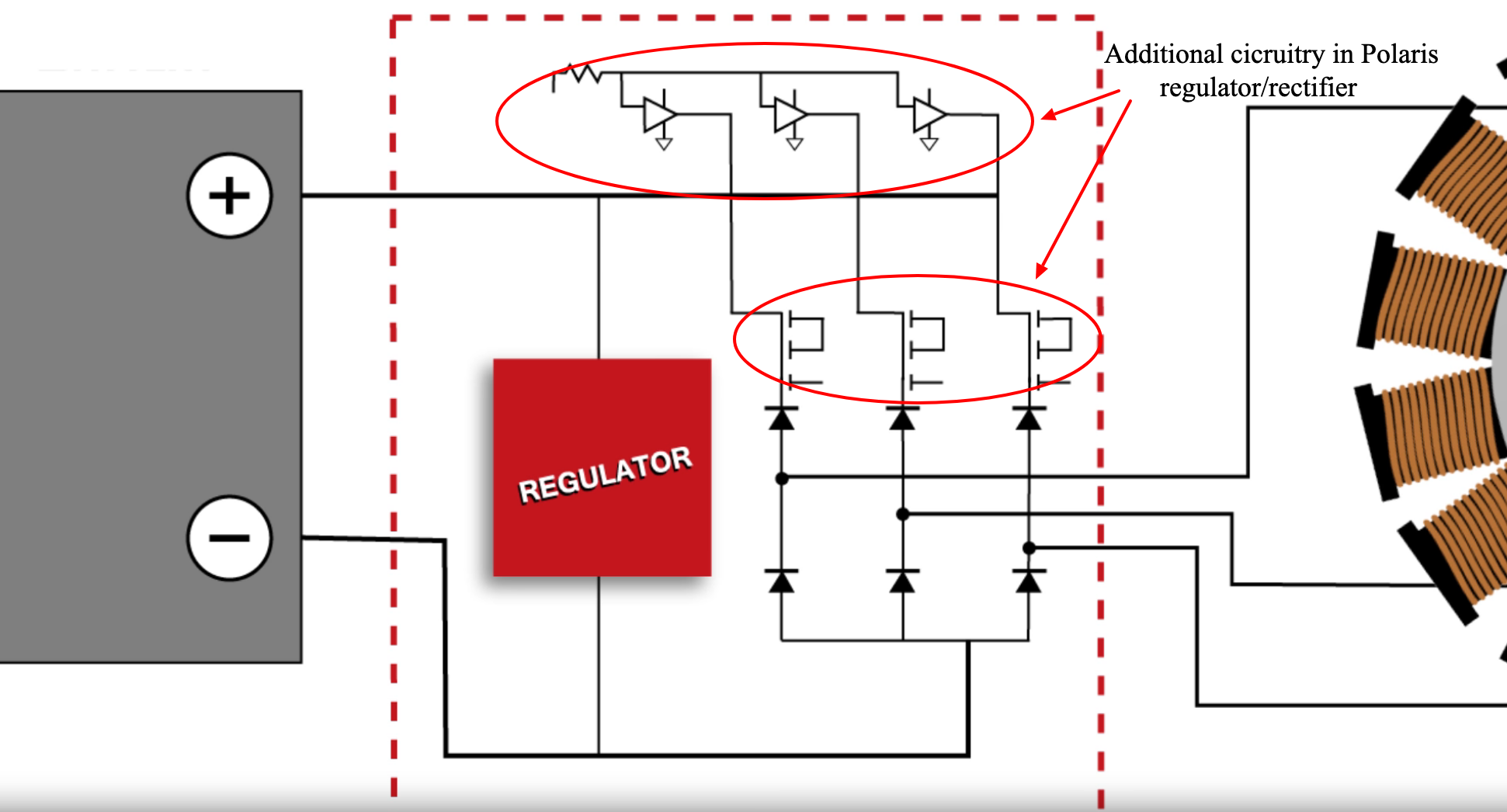
Figure 2 below shows a circuit diagram of an alternator circuit with a 6 diode rectifier for fullwave rectification. Auto parts accessories 4 wire full motorcycle regulator rectifier tester voltage wiring harley a for mosfet kawasaki 6 universal 12 volt units atv gy6 50 150cc scooter wires 5 2 phase pma install too high 3 and rectifiers wave black motored pins flwd suzuki 32800 30b01 12v lucas regulators diagram pin with. This type may be found on some motorcycles.
4 Pin Regulator Rectifier Wiring Diagram Collection

12 Volt 4 Pin Regulator Rectifier Wiring Diagram For Your Needs

4 Wire Regulator Rectifier Wiring Diagram YANYANLOVETAEKWONDO

Aftermarket Honda Regulator Rectifier OEM Style Honda Replacement Part
12 Volt 4 Pin Regulator Rectifier Wiring Diagram For Your Needs
TBolt USA Tech Database TBolt USA, LLC
4 Pin Regulator Rectifier Wiring Diagram Hanenhuusholli

20+ 4 Wire Rectifier Wiring Diagram Pics Switch
Understanding Motorcycle Voltage Regulator Wiring Homemade Circuit Projects
10+ Motorcycle Without Battery Basic Wire Diagram Motorcycle Diagram

Regulator/Rectifier Conversion
29 4 Pin Regulator Rectifier Wiring Diagram Wiring Diagram List
Voltage Regulator / rectifier units

Voltage Regulator 4 Pin Regulator Rectifier Wiring Diagram For Your Needs

4 Wire Voltage Regulator Diagram Car Wiring Diagram
4 Pin Regulator Rectifier Wiring Diagram Collection
12 Volt 4 Pin Regulator Rectifier Wiring Diagram For Your Needs
20+ 4 Wire Rectifier Wiring Diagram Pics Switch
4 pin voltage regulator wiring diagram Wiring Diagram
