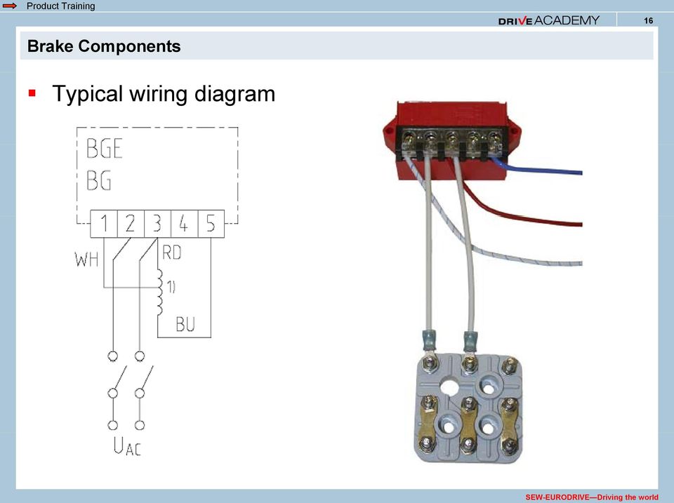
Nord Brake Motor Wiring Diagram
Break away systems may be added to the service brake circuit. The friction and inertia of the system).
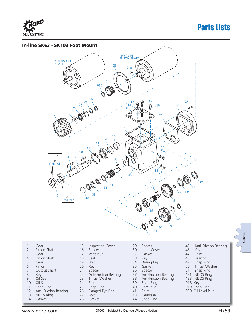
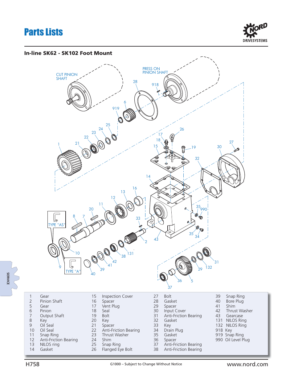
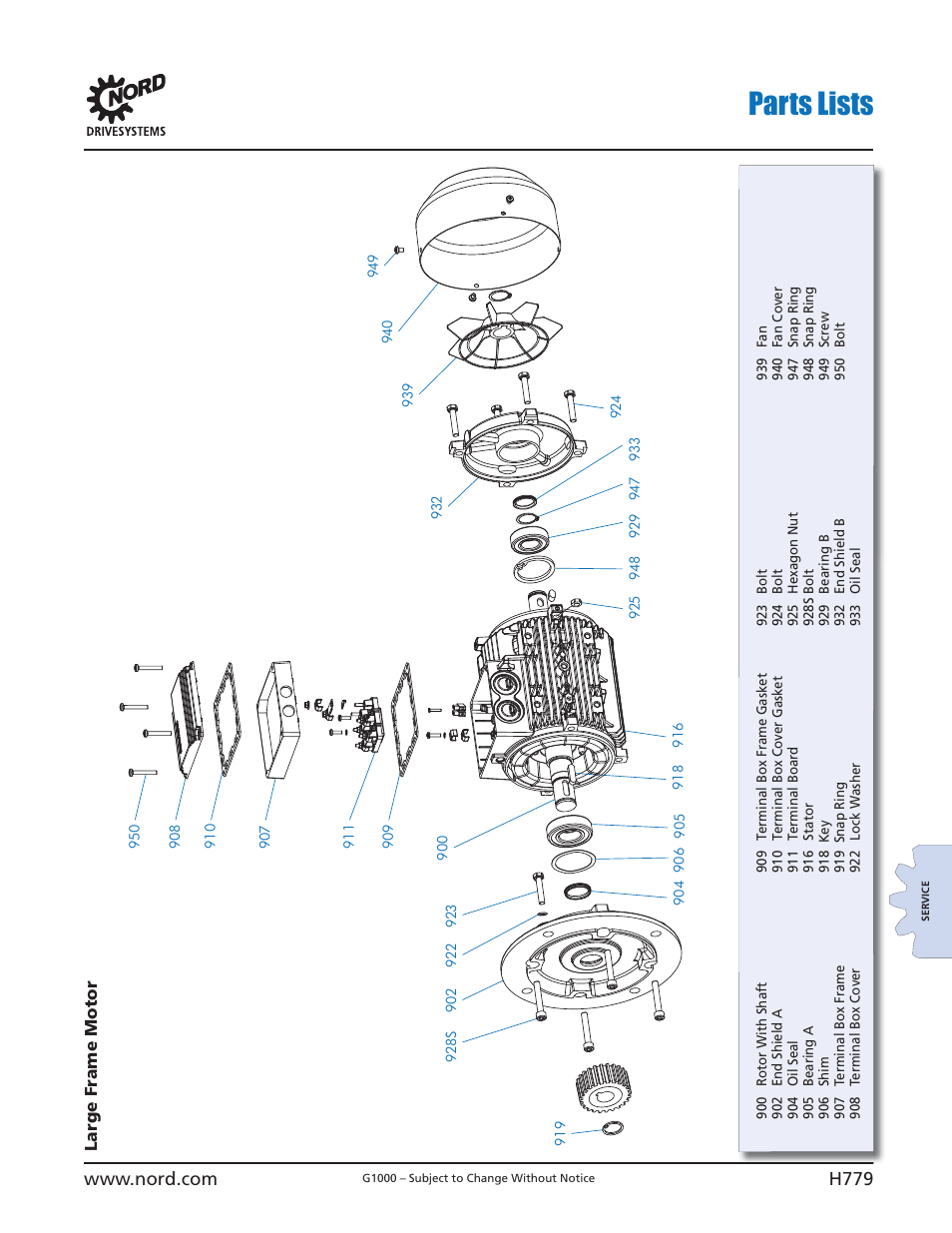
Parts lists NORD Drivesystems B1000 User Manual Page 761 / 820
The terminal box lower section as well as the is lower section are referred to as adapter plate in the parts lists.
Nord brake motor wiring diagram. If the operating current of the unit is high, and the motor inductance is low you may hear the circuit breaker buzzing when the brake is applied. Is a subsidiary of m.g.m. Symbols that represent the ingredients inside the circuit, and lines that represent the connections between.
Terminal markings and internal wiring diagrams single phase and polyphase motors meeting nema standards see fig. 2002 ford ranger rear brake diagram you should see four pictures pop up, select the brake parts diagram or the brake picture. How to wire a three phase motor.
The original wiring diagram showed the proper arrangement of windings to create a larger wye system in which there are four equal windings between any two leads. • the standard brake, which is optionally integrated in drc. Welcome to mgm electric motors north america.
I need a diagram for the rear drum brake for 2002 ford ranger. The brake control must be installed with a 12 volt negative ground system. 1999 ford ranger rear brakes diagram.
In the united states, for low voltage motors (below 600v), you can expect either 230v or 460v. A wiring diagram is a schematic which uses abstract pictorial symbols showing each of the interconnections of components in the system. Which allow the motor brake system to cycle at a very high rate.
100 frame motor with 4 poles, brake, 100 nm with a hand. In addition to various connection voltages, brake controls for specific application requirements are available as well: An electromechanical brake is controlled and released with this dc voltage.
Wiring diagrams are made up of certain things: 888.314.6673 nord gear limited toll free in canada: Is not only a primary source of metric motors but is also the main source for all those.
Brake motor wiring diagram best nord exceptional sew eurodrive on this website we recommend many images about sew eurodrive wiring diagram that we have collected from various sites from many image inspiration, and of course what we recommend is the most excellent of image for sew eurodrive wiring diagram. Read and follow all instructions carefully before wiring brake control. The wiring diagrams show c type circuit breakers as the protection for the brake modules.
Usually, the brake is controlled by a brake control that is installed in either the motor terminal box or the control cabinet. Circuit breakers are convenient, but may not be suitable for the application. 3 phase electric motor brake wiring diagram.
Keep wire cap on lead wire end not used. You find information on how to wire the upper part of the is plug connector in the ac motors/ac brake motors operating instructions. You can choose from a wide range of brake controls.
Once you do you are able to read diagrams quickly and can often understand a circuit at a glance. I thought the wiring would be similar to that used previously on my drill press, however this saw's motor has an electromagnetic brake installed in it. In these cases a d type breaker.
Electric motors north america inc. If the air gap exceeds the maximum allowed for that brake configuration provided in the manual, adjust the air gap Keep these instructions with the brake control for future reference.
Generic wiring diagram read this first: Posted on sep 03, 2009. Electric motors north america inc.
Important facts to remember 1. That being said, there is a wide range of different motors and what you have on hand. It is not part of the safety functions mentioned above.
• the detailed operating instructions and wiring diagrams. The bme can we wired to operate for. The brake rectifier converts the mains voltage into a dc voltage.
Connect the brake supply cable inserted into the motor terminal box according to the diagram on the inside of the box cover, while connecting the brake with the motor maintain all the necessary safety measures and precautions pertaining to the handling of electrical equipment, 9. Connection diagram dt79 example motor voltages: Mounting the motor casing onto the brake and fan completes.
Electric brake controller wiring diagram. If the brake controller and/or the motor brake fails, the drive can coast for much longer depending on the application (i.e. Auxiliary connection is optional, it may be connected to any 12v to 24v constant power source or left unconnected.
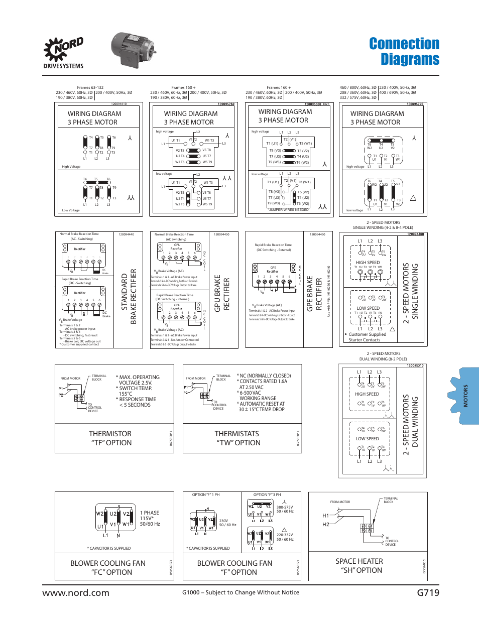
Usa u5 v5 w5 l1 l2 l3 u2 v2 w2 t6 t1 t2 t3 t4 t5 u1 v1 w1 t7 t8 t9 u5 v5 w5 motor connection diagrams uscs 0100. Copy and paste this into your search window: The first step is to figure out the voltage of your phases.
The power supply to the brake is interrupted by switching off the mains voltage.
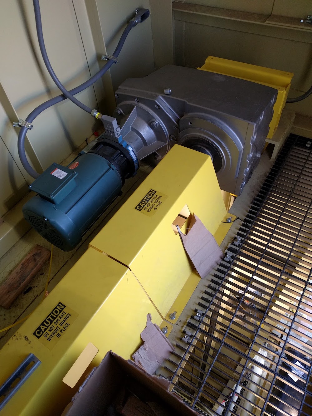
Application VRC Vertical Reciprocating Conveyor A R Young Company
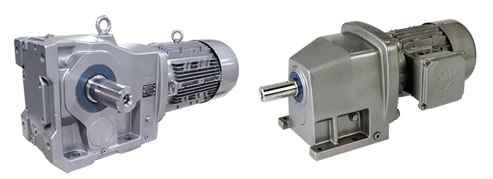
NORD DRIVESYSTEMS Industrial Technology
40 Nord Motor Wiring Diagram Wiring Diagram Online Source

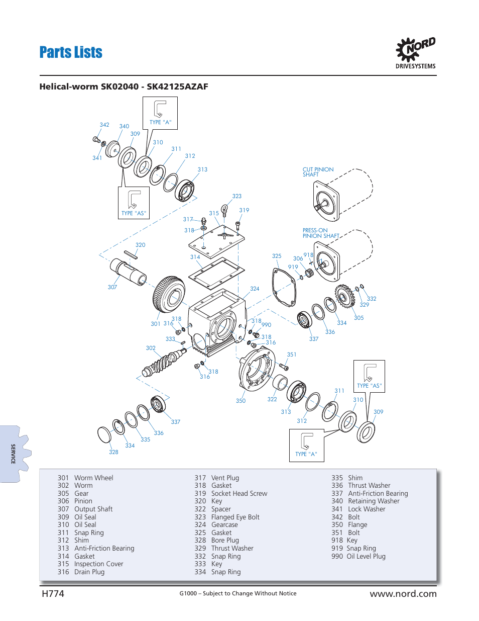
Parts lists NORD Drivesystems B1000 User Manual Page 776 / 820
Nord Drivesystems 4.481 Gear Reducer Type SK3282AZH66 180TC2 eBay

Connection diagrams, Brake rec tifier st and ard, Rec tifier gpu brake NORD Drivesystems B1000
WEG Electric IEC Enclosed Motor Starters State Motor & Control Solutions

Bodine Electric 0645, Right Angle AC Gearmotor, .167 HP, 340 RPM

Eurodrive Brake Motor Wiring Diagram
Adaptation above size 8, 3 electrical connections, power unit, Electrical connections, power

Nord, SK80L/4 CUS BRE20 FHL RG IR, 1SIS50N56C, 2000996014300 Brake Gear Motor Worm Reducer

Alfa Romeo 1750 Gtv Wiring Diagram Wiring Diagram Networks

Parts lists NORD Drivesystems B1000 User Manual Page 760 / 820
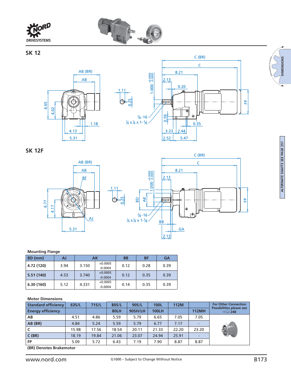
Sk 12 + motor sk 12f + motor, B173, Sk 12 sk 12f NORD Drivesystems B1000 User Manual Page
Parts lists NORD Drivesystems B1000 User Manual Page 781 / 820
Motor Control Panel Wiring Diagram Gallery Wiring Diagram Sample
40 Nord Motor Wiring Diagram Wiring Diagram Online Source

Inverter related options NORD Drivesystems B1000 User Manual Page 705 / 820
Alfa Romeo 1750 Gtv Wiring Diagram Wiring Diagram Networks